Creating an Inspection Regime
Creating a System
Systems are a way of grouping assets. For example, in legionella compliance monitoring there may be systems such as Domestic or Cooling Towers. Other examples of systems are fire suppression systems or electrical systems. Velappity comes preconfigured with several systems but you can set up your own system if required. To create a system, select the “Settings > Systems” menu item which will open the “System List” page.
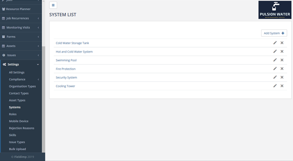
On the “System List” page a list of all the systems is displayed. To create a system, the user must press the “Add System” button at the top right of the page:
Once the “Add System” button has been clicked, the user will be taken to an “Add System” page:
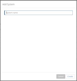
To add the system, the user must enter the name of the system i.e. Domestic Water System, then the user must click the “Create” button.
Assets
An Asset is a piece of equipment upon which inspections or tests are performed. Generally, in a compliance regime, an Asset Type is used to categorise assets. For example, an asset type could be fire extinguisher, and there may be many fire extinguishers (Assets) on the site i.e. fire extinguisher 1, fire extinguisher 2. Asset types are used to determine which inspection test is relevant when creating an asset on the site. For example, an inspection test may check that the pressure within a fire extinguisher is within parameters and this test may be performed quarterly on all assets of asset type fire extinguisher. Before creating an asset, a corresponding asset type must be made.
Creating Asset Types
Asset Types define the class of asset when an asset is created (e.g. Hot Water Tap, Shower, Cooling Tower or Electrical Panel). Asset types group assets together so that particular tests can be run against them. For example, you can set up tests, see later, to be performed on all assets of a particular asset type. To create an Asset Type, the user must select the “Settings > Asset types” menu :
Once this is clicked, the user will enter the “Asset Types List” page:
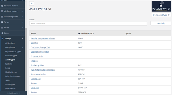
On this page, the user is able to see all of the asset types that have been created. As well as being able to create, edit and delete the asset types.
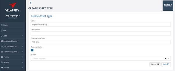
Clicking the “Create Asset Type” button displays the “Create Asset Type” page:

The user should enter the name of the asset in the “Name” field, for example Fire Extinguisher or Hot Water Tap. The user can also include a brief description for the asset type if they desire in the “Description” field. The “External Reference” field is a unique string of letters and/or numbers which uniquely identifies this asset type for external use (this is often used for integration with external systems).
The user can also determine whether or not the field is “Representative” for more information on this please see the “Representative Outlets” section below.
The “System” field includes the system that the asset type belongs to (see the “Creating a System” subheading in the “Compliance Module” heading if the user is unsure as to what this is / wishes to create a system). Once the user is happy with the inputted information the user must click the “Save” button at the bottom right of the page to save the asset type, meaning that it will not be able to be seen in the asset type list and be able to be used when creating assets.
![]()
Clicking the asset type name will take the user to an edit page, where the user can edit or delete the asset type:

Note that an asset type CANNOT be deleted if it has assets of this type within Velappity.
Creating Assets
To create an asset, the user must click on the “Assets” heading, followed by the “Create” sub-heading:

The user will then be met with a prompt with a dropdown menu, asking for an asset type to be selected. Simply select the asset type that corresponds to this asset:
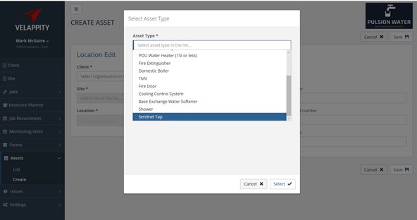
Following this, press the “Select” button to select the asset type. The “Create Asset” page will then be displayed.
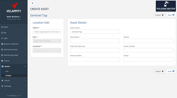
An asset will exist on a client site at a specific location (e.g. client could be Acme Ltd with the site being the London site and the location being the Plant Room).
On the left-hand side of this page, the user will be able to fill in details of the location of the asset through a series of dropdown menus. A Client, Site and Location should already exist before creating the asset (see the relevant sections on how to create a client, a site and a location.
From the “Client” dropdown menu, select the client that this asset belongs to. If this client is not in the dropdown menu, see the “Client creation” section in this document. For the “Site” dropdown menu, select the site of the client that the asset is located in. If the site is not in the dropdown menu, see the “Creating a Site” section in this document. For the “Location” dropdown menu, select the location in the site where this asset is located. If the location is not in the dropdown menu, see the “Creating a Location” section in the document.
On the right-hand side of this page, the user will be able to enter details on the asset. The “Asset name” field will have already been filled out for the user as this should be the asset type, however this will usually need to be edited to uniquely identify the asset. The “Description” field is a description of the asset, the “Owner” field is the owner of this particular asset. For example, an asset may be legally owned by the client or a third party and this ownership can be recorded here. The “External Reference” field is a unique string of numbers and/or letters that uniquely identifies the asset for external use.
The “Asset Number” field is the unique number given to an asset which helps it to be identified in the asset list. The “Serial Number” is another string of letters and/or numbers that can be used to uniquely identify an asset, this will be located on the asset. The “Notes” field is there if the user wishes to add any comments etc to accompany the asset.
Clicking on the “Save” button will create the asset.
Representative Outlets
To create representative and sentinel outlets in Velappity, the user should make an asset type for each. Asset types are sentinel by default, to create a representative outlet the user should make sure the “Representative” checkbox is checked when they are creating the asset.
Creating a Measurement Type
A measurement type is a class of measurement that tests are performed against (e.g. temperature, pressure, resistance, pH, etc). To create a measurement type, select the “Settings > Compliance > Measurement Types” menu and the “Measurement Type List” page will be displayed.
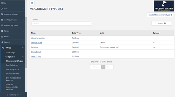
Here, you will see a list of all the measurement types that have previously been created. To create a new measurement type, the user must press the “Create Measurement Type” button in the top right of the page. This button will display the “Create Measurement Type” page:

On this page you can enter new measurement type. The “Measurement Type Name” field is the name of the measurement type e.g. Temperature or Length.
The “Data Type” field is the type of data that will be entered for this measurement type, with this being a dropdown menu of the choices; integer, boolean or decimal. Integer values are positive whole numbers (e.g. 5 or 123), boolean values are either true or false (generally used for check if something is present or not) and decimal values are numbers which are non-integer numbers (e.g. 9.9 or 22.5). The “Min” field is the smallest value that is expected to be entered for this measurement type, for example length would have a min value of either 0 or 1. The “Max” field is similar to the “min” field, however, it is the largest value that is expected to be entered for the measurement type. The “Unit name” is the units that you are dealing with, for example if the user was measuring length, the unit name could be metres, or for temperature the unit name could be Celsius. Similarly, the “Unit Symbol” field works in unison with the “Unit Name” field as it is the unit name’s symbol e.g. Kilometres is Km. Once this page has been filled out, to complete the addition of the measurement type. Clicking the “Save” button will save the measurement type.
Creating a Test Definition
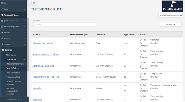
A test definition allows you to define a test (e.g. when temperature is less than 50C raise an issue). Through using test definitions, the user is able to set up issues on pass or failure of this test. Issue types must be created before setting up a test definition (see Creating An Issue Type). To create a test definition, you select the “Settings > Compliance > Test Definition” menu which displays the “Test Definition List” page.

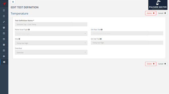
On the “Test Definition List” page, there is a list of all the previously created test definitions. If the user wishes to delete the test definitions, the user must click on the name column on the test definition. This will take the user to the “Edit Test Definition” page, where the user can delete the test definition by clicking the “Delete” button at the top right of the page:
As well as this, the user is able to create a “Test Definition”. The user can do this by clicking the “Create Test Definition” button in the top right corner of the page:
After clicking this button, the user will be taken to a popup window which will ask the user what the measurement type is for this test:
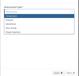
The user can select the measurement type from the drop-down menu provided and then press the “Select” button.
After the user presses the “Select” button. The user will be taken to the “Create Test Definition” page:

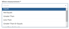
The user can then enter information on the test definition. The “Test Definition Name” field is the name of the test, the “When Measurement” field is a conditional field which is used to report an issue, this has a dropdown menu of the following values:
- Equals
- Not Equals
- Greater Than
- Less Than
- Greater Than Or Equals
- Less Than Or Equals
- Between
The “Value” field is the value that assists the “When Measurement”, for example when the measurement equals 3 . In this case “ ” would be the value used in the test definition. The “Raise Issue Type” field raises an issue, which has been created by the user (see “Creating an Issue” in the “Compliance” section) when the conditional statement is True based on the “When Measurement” field and the “Value” field.
For example, if the “When Measurement” field is set to greater than and the “Value” field set to 20 then when the measurement is greater than 2 the statement is true. In this case the issue type in the “Raise Issue Type” field will be raised. If the statement was false (e.g. where a test value was less than or equal to 20) then the issue type in the “Else” field will be raised.
Tests are generally done on values as they are entered by filed inspectors on their mobile devices. The “On Pass Text” field allows the user to enter text that will be displayed to the field inspector when the test is passed. The “On Fail Text” field is used to enter text which is displayed to the mobile user when a test is failed. The “Overdue” field is used to select the issue type to be raised when this test becomes overdue (see “Create Test Frequency” below for information on setting test frequency).
This entire setup allows the flexibility of creating tests which can raise issues on passing, failing or becoming overdue. Generally, most applications would only want to raise issues on failure or tests becoming overdue.
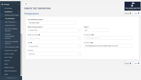
Clicking “Save” will save the test definition.
Creating a Test Frequency Tag
Test frequency tags are used to group tests on the mobile device and are needed to create a test frequency. To create a test frequency tag select the “Settings > Compliance > Test Frequency Tag” to display the “Test Frequency Tag” page.
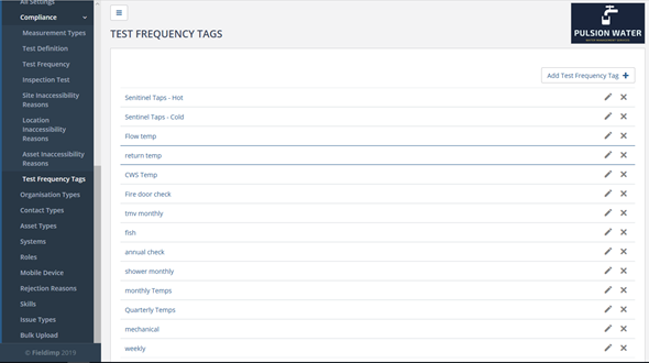
Once the “Test Frequency Tag” has been clicked, the user will be taken to the “Test Frequency Tags” page where the user will be able to see previously made test frequency tags. As well as being able to edit them and delete them. To delete a test frequency tag, the user must press the delete symbol (the cross) next to the specific test frequency tag in the “Test Frequency Tags” page. To edit a test frequency tag, the user must press the edit symbol (the pen) next to the specific test frequency tag.

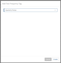
To display the “Add Test Frequency Tag” page, the user must press the “Add Test Frequency Tag” at the top right of the “Test Frequency Tags” page.
The test frequency tag (e.g. Quarterly Temps) can be entered and saved by hitting the “Create” button.
Creating a Test Frequency
Test frequency ties together test definitions along with asset type and a periodicity. For example, if we want to perform a hot water temperature test on the hot water tap asset type on a monthly schedule. When we are scheduling a test regime for a site then the test frequency is used to create and schedule tests for all the different asset types present on the site.
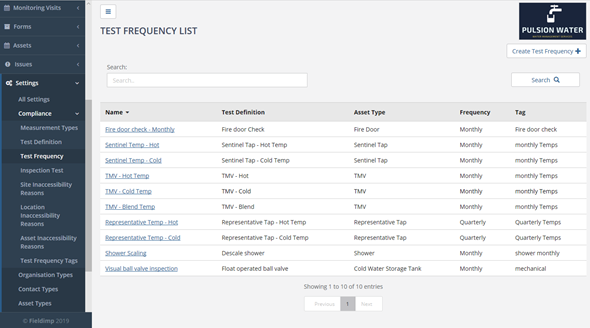
In order to create a test frequency, the user must create an asset type (see “Creating Asset Types”), a test definition (see “Creating a Test Definition”), and a test frequency tag (see “Creating a Test Frequency Tag”) first. To create a test frequency, click on the “Settings > Compliance > Test Frequency” menu to display the Test Frequency List page.
The “Test Frequency List” page allows test frequencies to be created, deleted and edited.

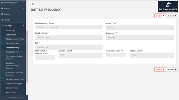
Clicking on the name of a test frequency in the list will display the “Edit Test Frequency” page.
To create a Test Frequency, click on the “Create Test Frequency” button in the top right of the page:
Once clicked, the user will be taken to the “Create Test Frequency” page:
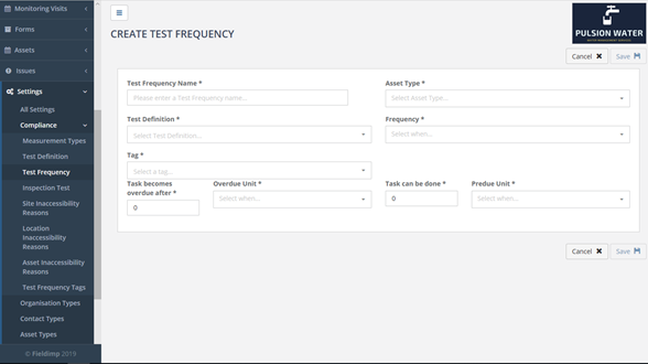
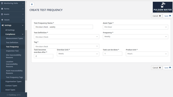
On this page the “Test Frequency Name” field is the name of the test frequency. This will usually have the same name as the test definition plus a time period (e.g. Quarterly Pressure Check). The “Test Definition” field is a dropdown menu of all the test definitions which have previously been created, appropriate test definition must be selected. The “Asset Type” field is a dropdown menu of all the asset types which have previously been created, the user must click on the appropriate asset type. The “Frequency” field is a dropdown menu which is used to state how often this test will be carried out, for example, monthly or annually.
The “Tag” field is the Test Frequency Tag which is used for grouping tests together on the mobile device. The “Task Becomes Overdue After” works in conjunction with the “Overdue Unit” field. With the “Task Becomes Overdue After” allows the user to enter a number and the “Overdue Unit” field allows the user to pick a unit of time from a dropdown menu i.e. months. These two fields work together to define after how long after the job has been set that the job becomes overdue. Similarly, the “Tasks Can be Done” field and the “Predue Unit” work together. The “Tasks can be Done” field allows the user to enter a number and the “Predue Unit” allows the user to pick a unit of time from a dropdown menu. These two fields work together to define how many units of time before the scheduled date the job can be completed i.e. the job can be completed 1 day before the job is scheduled. Clicking the “Save” button will save the test frequency.
Creating a Monitoring Visit
Monitoring visits are special types of jobs. Monitoring visits can be scheduled to occur regularly on a site (e.g. every week starting 1/1/2018 until 31/12/2020). What makes monitoring visits unlike other Velappity jobs is that the monitoring visit checks the Compliance module to see whether any inspection tests are due on assets.
Inspection regimes on a site start when the first monitoring visit is scheduled.
To display the “Create Monitoring Visits” page, select the “Monitoring Visits > Create” menu. This page has two separate sections, “Details” and “Recurrence Patterns”.
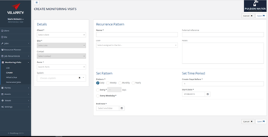
To fill out the “Details” section, the user must select the “Client”, “Site” and “Form” field at least. The “System” field is a dropdown menu of all of the systems that are on the Velappity system e.g. Cooling Tower. The user should choose the system that is applicable to this monitoring visit. If the “System” field is left blank then the monitoring visit will cover all systems on the site.
The “Client” field is a dropdown menu of all the clients on the system, so the user should select the client that this monitoring visit is applicable to. The “Site” field is a dropdown menu of all the sites that are on the system that the user has entered previously. The user should select the site that this monitoring visit is applicable to. The “Contact” field is the contact that is situated at the site, this is a dropdown menu and will depend on what site the user previously selected. The “Form” field is a dropdown menu of all the forms in the system, the user should select the form which is applicable to this monitoring visit.
To fill out the “Recurrence Pattern” section, the user must fill in at least the “Name” field and the “Set pattern” and “Set Time Period” sections. The “Name” field is the name that the user wants to give to the monitoring visit e.g. “Weekly Fire Door Check”. The “External Reference” field is a unique string of letters and/or numbers that uniquely identifies the specific monitoring visit recurrence pattern. This reference is created by the user.
The “User” field is a dropdown menu of all the users on the system e.g. surveyor, this field should be set to whichever user should be carrying out these monitoring visits. If left blank then the user can be assigned when the monitoring visit is assigned.
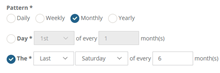
The “Notes” field is a space where the user can enter any comments on the monitoring visits for the user (e.g. surveyor). The “Pattern” label is used to outline how often the monitoring visit will happen. To set up the pattern, the user must first click on one of the checkboxes from the tab of checkboxes just below the pattern label:
![]()
The daily checkbox is for monitoring visits that need to occur every couple of days, when the daily checkbox has been activated, two new checkboxes will appear below the tab of checkboxes:
To select a set number of days that are between each monitoring visit, the user must click on the checkbox entitled ‘Every XXX days’. At this point, the user is able to change the number of days between monitoring visits through the textbox. Otherwise, if the user wishes to set each monitoring visit to being on every weekday, the user can click on the checkbox to the left of the “Every Weekday” text.
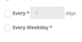
If the monitoring visit is weekly, the user can click on the “Weekly” checkbox in the “Pattern” tab.
![]()
This will then bring up a section, in which the user can enter how many weeks are between each monitoring visit and what day/days of the week the monitoring visit will be on.
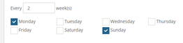
If the monitoring visit is monthly or every couple of months, the user should click on the “Monthly” checkbox in the “Pattern” tab.
![]()
This will bring present the user with two checkboxes below the “Pattern” tab, these are used to differentiate between monitoring visit frequencies
![]()
The user should use the top checkbox if the frequency of the monitoring visit is a certain date on every month, for example, the 15th of every month. Whereas, the user should use the bottom checkbox if the user wishes to set the frequency of the monitoring visit to be on a certain day of that month, for example the 2nd Friday of every month.
The “End Date” field is the date that the user would like the monitoring visits to stop being carried out, for example the user could set up a weekly monitoring visit every Tuesday. However, these weekly monitoring visits could be set up to finish on the 30th August. This field will bring a calendar up when the user clicks on the field, then the user is able to choose a date when the monitoring visits will end. The “Create Days Before” field outlines the number of days before the day that the job should be completed that the job is created for the monitoring visit. The “Start Date” field is the date that the monitoring visits will begin and is the date that applies to some aspects of the “Set Pattern” section as the frequency starts from the starting date. Once the user is happy that all the information is correct, the user should then click on the “Save” button to create this monitoring visit plan.
To determine when monitoring visit jobs are due, the user should click on the “Monitoring Visits > What’s due” menu :
This will then take the user to the “What’s Due” page:

Here, the user is able to see the last time the job was completed and when the next date that the job is due. In this example, the “Monthly Temperature Monitoring” site visit is due on 24/08/2019. On this page, it is possible for the user to view the monitoring visit on its monitoring visit page. This can be done by clicking on the site visit’s link in the “Name” column.
